
"TT-Tracks©" Standards
 |


|
|||||


 |
||||||
"TT-Tracks©" Modular System Standards
Version 2.1 - November 27, 2018
The following are the TT-Tracks Standards. Permissable variations are noted.
Click on Image for larger Size.
Basic Modules
| * Minimal Standard * | |||||
| . | . | There are two specifications that a module Must adhere to to work in a TT-tracks setup.
|
|||
| * Specifications Common to all Modules * | |||||
| . | - Height | ||||
| . | . | The base board height is 2 3/4". It is suggested that you have legs with levelers on them to handle variations in table top surface. | |||
| - Fascia | |||||
| A fascia should be mounted on the front and back sides to hide the underside of the module. This could be permanently attached or (better) added on after the module is leveled. | |||||
| . | . | . | Note - I have found that styrene makes a good light fascia; .060" works well. |
||
| = Backdrop - Optional | |||||
| An optional back drop that extends one foot above the base surface may be added to the rear of the module. Whether this is used or not will depend on the setup. | |||||
| - Colors | |||||
| The base color shall be a dirt brown color or grass green. | |||||
| The brown can be any dirt like colour. It is not important. The purpose of the brown is have colour under any scenery material in case the scenery material gets scrapped off. The brown will show instead of the foam or wood colour | |||||
| The fascia color shall be Rust-Oleum Satin 'Hunt Club Green'. | |||||
| This color is readily available in North American. European
modelers will establish their own color standard based on what is available there. When a color
and brand of paint is chosen please let me know and I will add it to these standards.
I have been using a Tamiya Spray paint for the fascia. TS-43 Racing Green. |
|||||
| - Power | |||||
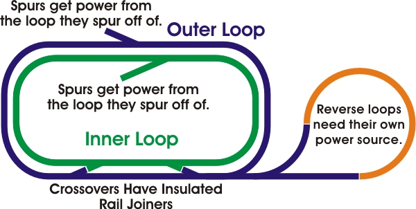
| A small oval display will receive its power from connections on one corner rmodule. | |||||
| Side modules will receive their power through the rail joiners from a corner module. | |||||
| On larger displays a power cable will feed power to the corners. | |||||
| As of September 2018, displays will receive their power from a dedicated power module with cables feeding power to the corners. | |||||
The two tracks shall be electrically isolated from each other. Spurs will have
power fed from the line they spur off of.
|
|||||
| * Straight Modules * | |||||
| - Standard Straight Module | |||||
| . | - Length | ||||
| . | . | A standard straight module is 497mm long | |||
| . | . | . | Derivation of length: The Standard Straight track piece (BG 1 -
166mm) is used to determine the length of a standard straight module. It is 3 track lengths
long less 1mm. That is 497mm long. This is the maximum length for a standard three track
segment module. Any longer and the track connectors will not mate properly. The 1mm
deduction is to allow the connectors to hang out far enough to connect to the next module. If the
module is longer than that the connectors will not stick out far enough to connect properly with
the next module. Too short and there will be an unsightly gap between modules.
A length of three pieces was chosen as this is long enough to have a single crossover and another turnout as a spur. It is also very easy to transpot. |
||
| = Permissible Variations in Length
As we are no longer doing closed loop displays, modules may be any length needed for the scene you are building. Be aware that larger modules may have transport issues. |
|||||
|
For 'Donut' setups if someone makes a module of non-standard length it is up to them to make
sure the necessary filler module is available to make the oval work.
A setup coordinator may want to have filler modules of one track length (BG1) and two track lengths (2 x BG1) on hand to allow for odd sized modules. |
|||||
| - Depth | |||||
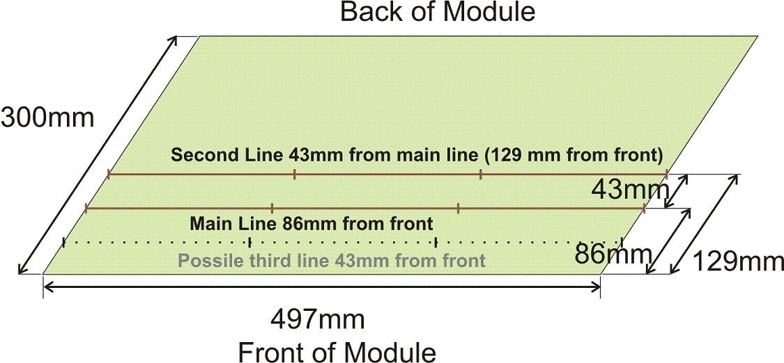
| The size of a standard module will be one foot in depth | |||||
| 30cm is an accepted variation on 12" | |||||
| 30cm may be easier to make for our European members. As well some nominally 12" wide foam sheets are actually only 30cm wide. | |||||
| A 30cm (12") deep module could have six tracks on it. One in front of the mainlines, the two mainlines, and three behind the mainlines. | |||||
| Having modules the same depth makes for a coordinated display, however if the scene you are making requires it, there is no reason why the module could not extend to the front or rear. Be aware that this may complicate setting the display up on the tables usually provided by shows. | |||||
| - Track Location | |||||
| The center line of the front track shall be 86mm from the front edge of
the module. The centerline of the
second track shall be 129mm in from the front of the module (43mm back from the
second track).
The two mainline tracks shall be at right angles to the ends. Any other tracks you have may be at any angle to the ends but be aware of problems joining such tracks over module joints. |
|||||
| Getting the center of the track over the centerline has been a bit of
an issue. After determining the bedding track base was 31mm wide it was found easier to
measure to the front of the track. For unknown reasons the track has shifted to the rear about
1/4 inch on some modules.
New modules are being built to the standard. |
|||||
| * Corner Modules * | |||||
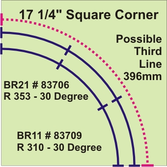
| - Small Corner Module - Sharp Curves - Deprecated. | |||||
|
|||||
| Size | |||||
| A standard corner module will be 17 1/4" square | |||||
| Track | |||||
| A standard Corner will have two quarter loops of track on it, one BR1 (310mm) and one BR2( 353mm). The ends of the track sections will extend approximately 1/2mm from the edge of the modules. | |||||
| The first setup has shown that curves on the small corner modules are too tight for North American Equipment. Short European equipment runs OK. | |||||
| Power | |||||
| Every second corner module should have power connections on it using #83951 - Rail Joiners with Solder tabs or Kato 24-818 Terminal UniJoiner, 35" Leads [1 pair]. | |||||
| The tracks shall be electrically isolated from each other. | |||||
| Service | |||||
| Used in the first setup in 2011. Due to their sharp curves, these module have been removed from mainline service. They are used in the reverse loop where they are only traversed at slow speeds. | |||||
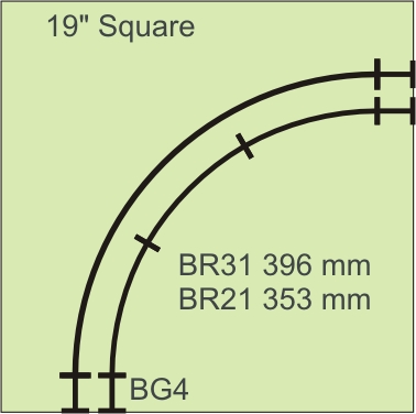
| - Medium Corner Module - Medium Curves - Never Built. | |||||
|
|||||
| Size | |||||
| A Medium Curve Module will be 19" square | |||||
| Track | |||||
| A Medium Corner Module will have two quarter loops of track on
it, one BR2 (353mm) and one BR3( 396mm).
The BR3 line will be made from Tillig #83111 - R 31 - Curved track: R 15 5/8" / 30 on a roadbed or from flex track on a roadbed.. Tillig now makes BR31 Bedding track Pieces. Because the R31 track pieces do not have the appropriate track connectors to join modules together, there will be a BG4 straight track piece at the end of each curve. The ends of the track sections will extend approximately 1/2mm from the edge of the modules. |
|||||
| Service | |||||
| These modules were never built as we jumped straight to the Broad Curve corners. | |||||
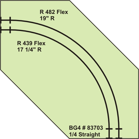
| - Large Curve Corner Module - Broad Curves - Formerly the Standard Corner Size for donut displays. Now depricated. | |||||
|
|||||
| Size | |||||
| A Broad Curve Module will be 24" square | |||||
| Because a 24" square module tales up a lot of space it is recommended that the front and rear corners be trimmed to make a diamond shape. | |||||
| Track | |||||
| A Broad Corner Module will have two quarter loops of track on
it, one a nominal radius of BR4 (482mm 19") and the other BR5 (439mm 17 1/4").
Both curves will be made from flex track on a road bed. Because the flex track does not have the appropriate track connectors to join modules together, there will be a BG4 straight track piece at the end of each curve. The ends of the track sections will extend approximately 1/2mm from the edge of the modules. |
|||||
| Service | |||||
| As of 2018 the Diamond corner (diagramed above) remains in service although a spruceup would be a good idea. Three other corners were built on 24" square wood painters canvases (neither 24" or square). These three are currently storeed useable. The wye corner still has its two mainline tracks, but other materials have been salvaged for reuse. | |||||
| Corner Module - 45 degree - 30" Square In occasional use in interior tracks. | |||||
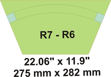 Curves are R6/R7 (nominal 20.7 in. and 22.4 in.) made from flex track with short bedding track pieces at the edges.
The edge clearance is a bit tight. A clear finger shield would be nice.
Curves are R6/R7 (nominal 20.7 in. and 22.4 in.) made from flex track with short bedding track pieces at the edges.
The edge clearance is a bit tight. A clear finger shield would be nice.
In service the curves look very good. The tips of the corners have been trimmed so they fit in a standard module transportation box. |
|||||
| Corner Module - 30 degree - R10/R11 Curves Built 2018 and used in 2019. | |||||
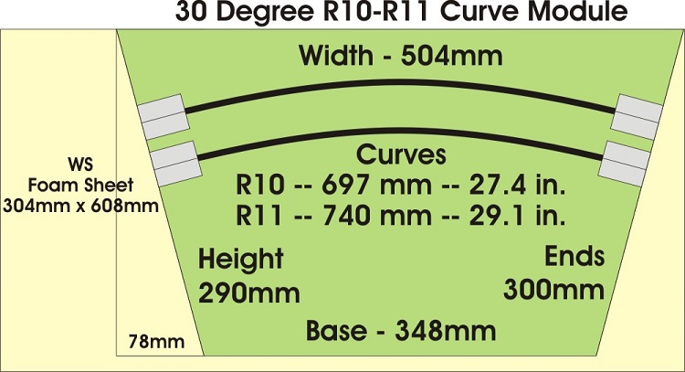
Built from flex track with short bedding track pieces at the edges. With R10 and R11 (nominal 27.4 in.and 29.1 in.) these modules look very good. This three part corner fits in a standard module transportation box. Now the standard corner with two sets ( three pieces) of basic curves and two set (four pieces) of curves with staging uard access. |
|||||
| Corner Module - 22.5 degree - R15/R16 Curves Built and used. Now stored servicable. | |||||
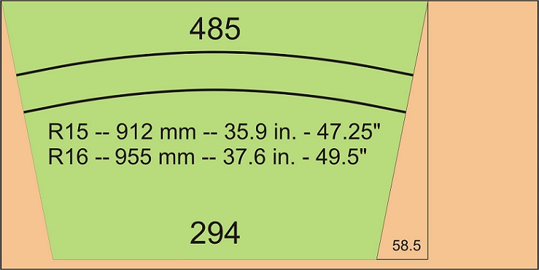
The curves are equivalent to 48" R in HO Scale. This four part corner would fit in a standard module transportation box. Built but stored servicable as they mess up the geometry of a donut dislay. They were built quickly so the curves are not as smooth as they could be. |
|||||
| Evolution of Corner Modules | |||||

We have come a long way since our early small corners. The original small 90 degree corners were too sharp for North American equioment. The first 90 degree large corner was used in our first display. The large 90 degree corners soldiered on as our standard corner for many years. In 2017 the 45 degree corner appeared and showed the way to the future. In late 2018 the first 30 degree corners were built. Designed to fit in a standard module transport box, these obsoleted everything that came before. In late 2018 a design for 22.5 degree corners was made. These also fit in a standard module carrying box. Built in 2019 and used for a setup or two. |
|||||
Standard Curve dimensions:
|
|||||
| End Loops | |||||
| End loops . | |||||
| As all early displays were variants on ovals, end loops were not needed. | |||||
| First Reverse Loop | |||||
| The first reverse loop was used on the 'Tadpoll' display. See diagram above for power.
It was built by Bjoern from two sharp corners and a few purpose built sections. With the shrp curves it was only suitable for slow speed operation. Later it was used as the return loop for the inside staging yard. |
|||||
| Service | |||||
| Stored servicealble. | |||||
| First Mainline Reverse loops. Now depricated. | |||||
|
|||||
| Size | |||||
| Two pieces: 36" x 30" and 24" x 30" hinged together: overall 60" Long by 36" wide at the widest part. Folds to a smaller package. | |||||
| Curve 15 5/8" nominal (R3). | |||||
| Track | |||||
| Built from Plyuwod.Hinged together with a paino hinge. Heavy. Awkward to move and setup. Curve 15 5/8" nominal (R3) made from flex track. This sharp curve was suitable for slow speed oeration. Used a Dual Frog Juicer as an auto reverser. Some thought was given to rebuilding these to R4 as some equipment did not operate well on R3 curves. |
|||||
| Service | |||||
| In service at Chilliwack in 2017. Served until replaced by the new foam based loops in 2019. One loop in service as the reverse loop for the inside staging yard. Other stored servicable. Heavy and awkward to store and transport. | |||||
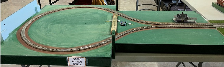
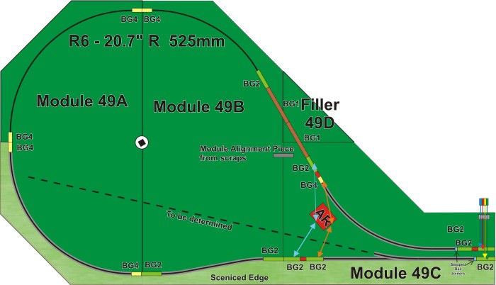
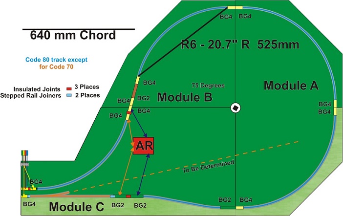
| 2019 new large multi piece return loops. | |||||
|
|||||
|
|||||
| Size | |||||
| Three pieses, plus a filler for one loop. Four feet wide by about seven feet long. | |||||
| Curve 20.7" nominal (R6). | |||||
| Track | |||||
| Built from multiple pieces of 1" foam. The teack is a mixture of bedding track, code 80 and code 70 flex track. Uses a Dual Frog Juicer as an auto reverser. |
|||||
| Service | |||||
| In service at BCSME June 22, 23 in a pre NMRA setup. In cureent use. | |||||
|
The first return loops broke us out of our donut displays into large more flexible setups.
Their sharp curves, weight and setup issues spurred development of new loops. These foam based, multi part loops are lighter with larger R6 curves. Locking mechanisms have been added to hold them together and properly aligned during operation. A hole was made in the center of the loops to accomodate the TT-Tracks Banner. Several ideas have been considered for scenicing the loops but nothing has come to fruition yet. |
|||||
- Flex Track on Modules
You can use flex track on your modules as long as they have a section of bedding track at
the edges to connect to the next module.
You can use a short piece (BG3, BG4 or BG5) or make your own by cutting up longer pieces.
I have had good success using a BG2 cut in half, then after the pieces are glued into place on the
edge of the module, removing the rails and running the flex track rails to the edge.
- DC Electrical
As we have been using DCC for every display since 2012, this section is deprecated.
DC is only suited for donut displays. Once you add reversing loops, it becomes impractical.
- DCC Electrical
One DCC system will be needed to operate the display. It should feed a power manager with two sections. One section will be used for each line of track.
| Displays have power fed to them through a power module.
This is daisy chained to the corners and other modules with power connectors.
One small corner had a power connector. All large corners had power connectors. One section of multi piece corners (45 degree, 30 degree, and to come: 22.5 degree) has a power connector cable. This cable has two sets of Anderson Power Pole connectors to eliminate the need for splitters. The orientation of the Anderson Power Pole shall be as illustrated. 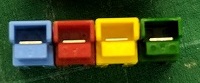
|
|||||
The power colour code is as follows:
|
* DCC Controlled Turnouts *
To prevent confusion on layouts with DCC controlled turnouts, turnout address space will
be allocated in groups of 20 addresses. This allows for some DCC Turnout controllers working in
groups of four.
When a builder needs a block of addresses they will request one and it will be logged here.
Where the builder has a DCC system that does not allow access to the full address range, things
will be adjusted so they get an address block that they can use with their system.
Current allocations are:
- 0 - Addresses 0 though 9 are unallocated to allow for modules at a display that have not been addressed properly.
- 1 - Bill Dixon = Addresses 10 through 29
- 3 - Bjoern = Addresses 30 through 49
- 5 - Tibi = Addresses 50 though 69
- 7 - __________ Addresses 70 through 89
- 9 - __________ Addresses 90 through 109
- 11 - __________ Addresses 110 through 129
- 13 - __________ Addresses 130 through 149
- 15 - __________ Addresses 150 through 159
- 19 - __________ Addresses 190 through 209
- 21 - __________ Addresses 210 through 229
- 23 - __________ Addresses 230 through 249
- 25 - __________ Addresses 250 through 269
- 27 - __________ Addresses 270 through 289
- 29 - __________ Addresses 290 through 309
- 31 - __________ Addresses 310 through 329
- 33 - __________ Addresses 330 through 349
- 35 - __________ Addresses 350 through 369
DC Accessory Power Buss
Deleted as it has never been used.
AC Accessory Power Buss
Deleted as it has never been used.
Accesories that need power will take it from the track.
Setup Guidelines
The SETUP COORDINATOR with design the layout to fit the space and tables offered.
Depending on the venue you may get 24" wide or 30" wide tables. 30" wide tables are easier to deal with. Tables may be six feet or eight feet long.Setup Guidelines for Donuts
As we now have end loops this section is depracated.
Setup Guidelines for loop to loop
A loop to loop display needs DCC. The power module should be located near the center of the display offset to the left to allow for the load of the staging yard. Power cables will feed power to the corners.
Setup Guidelines for Free Form
The main difficulty here is the length of the tables and the fact that they are rectangular. Using shorter tables will allow for more flexibility in the display. Having a few plywood bridge plates will allow you to place tables at non right angles and fill in the resulting gaps.
Supplies needed
As tables sag over time a selection of shims, both of plywood in various thicknesses and of matt board, are needed to level the tables and the modules on the tables.
One or two (preferred) extension cords are needed.
A basic tool kit with trucks, couplers, screws and glue will be useful. Basic scenery supplies; green paint, grass, glue, etc., should be on hand to touch up travel damage.
Signage, handouts, and other promotional materials should be to hand.

"TT-Tracks©" wordmark Copyright W.R.Dixon.
Contact Bill Dixon